2.3.4 Voltage/current clamping/patching
The very common measuring method reveals some fundamental differences between the electric behavior of conductors and living matter. ”The reason for voltage-clamping the axon is threefold: (1) By keeping the voltage constant, one can eliminate the capacitive current, that is, (2) by keeping the voltage constant, one can measure the time-dependent characteristics of ion conductances without the influence of voltage-dependent parameters; and (3) by inserting two silver wire electrodes into the axon, one can space-clamp it so that the whole length of the axon is isopotential (silver wires short-circuit the interior of the axon).” [2] That is: (1) the experimenter wants to make sure that does not change. A late consequence of choosing a wrong oscillator model. In the wrong model, the integrator, integrating the currents can be done and the voltage gradient has no role. In the correct model, the diffferentiator, the gradient controls neuron’s operation. (2) Clamping introduces extra current (not measured) to the neuronal circuit. From the known relations in Ohm’s law, we use the fixed voltage and the sum of the ’real’ current plus the ’foreign’ current, and attribute the observed deviation to that the conductance changed. Actually, the measurement device is not appropriate for that purpose. (3) As we discussed, the ion current is flowing on the thin layer on the internal surface of the axon. There are no charge carriers to deliver the potential from those electrodes to the stream of ions (the ions are pressed to the wall of the axon and the dielectric layer repulses the carriers). This effect is why Hodgkin and Huxley experienced [9] a time delay between a voltage and the current: the axon is not equipotential because it is not a conventional conductor. Again, physiology is resetting the clock: (1) they want to believe that voltage gradients have no role and so they eliminate it (2) the do not want to understand that voltage and current are not independent from the charge and the measuring device changes the measured value (3) they do not want to accept that the charge carrier and the charge transmission mechanism, and because of that, the behavior of the biological systems, are different from those in classical electronics. The low speed of ions hinderts the fundamental understanding, mainly of the temporal operation.
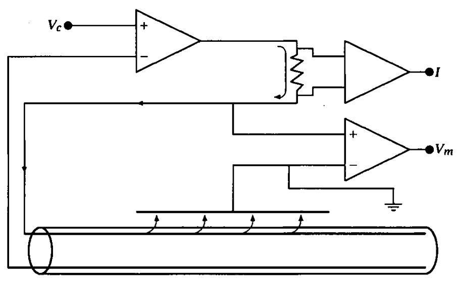
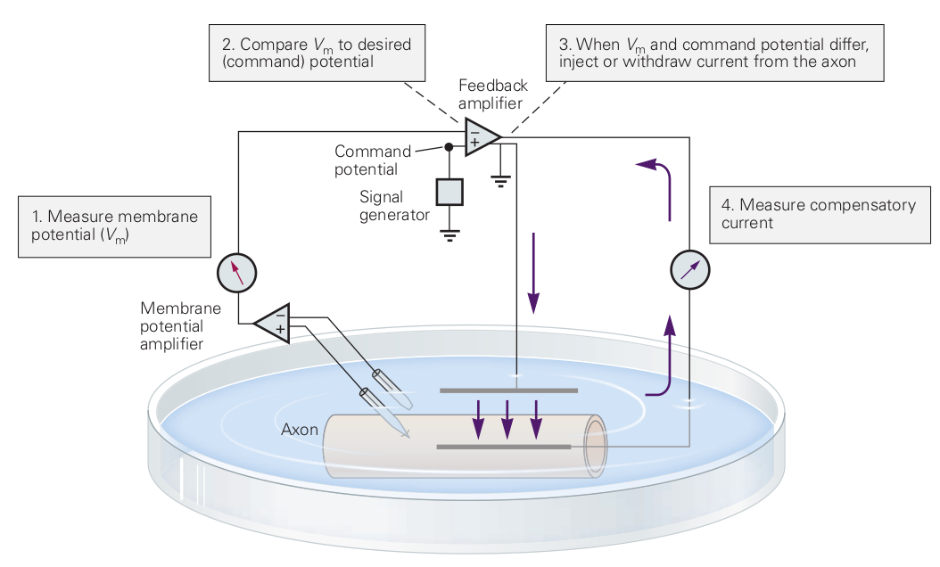
Notice two of the common fallacies in the figure. ”The highly conductive internal current electrode, which short-circuits the axoplasmic resistance, reducing axial resistance to zero”. First, the current flows in the thick layer on the internal surface of the membrane instead of inside the axon. The electrode keeps only the potential of the ”bulk” constant, unless the internal electrode fits perfectly (with better than the mentioned size accuracy) into the tube. Furthermore, the membrane’s surface can open/close ion channels in its wall, adding foreign current that causes a change in the value of the command potential. Second, there are two feedback amplifiers of the figure: the natural one (see Fig. 1.8) and the feedback in the clamp instrument. As we discussed, only the steady-state measurements can be accurate. The control voltage that is ”selected by the experimenter and can be of any desired amplitude and waveform”, is misleading: when using non-constant waveform, the system is not in steady state.
See Figure 1.8: ”Any conductor that has a linear current-voltage (I-V) curve is said to be ohmic. Not all conductors have linear I-V curves. Most neurons, for example, have nonlinear or nonohmic I-V relations.” The neuron is not a simple conductor. ”Only a narrow region of the V-I or I-V curves of a neuron can usually be considered ohmic.” [2], page 488. When studying its behavior using ’foreign’ voltage or current, outside that narrow region. The measuring procedure may trigger neuron’s own electric processes, and the careless experimenter observes that – from his point of view – ’foreign’ contribution as a deviation from the ohmic relations. See examples in section 3.2. ”The construction is different from anything we have yet tested in the physical laboratory” [12]; we need to use different methods for that different construction.